What is CFD
CFD stands for Computational Fluid Dynamics. It is a branch of fluid dynamics which solves fluid flow problems using computer (simulations). The logic behind the operation of CFD software is complex and explaining it would require a complete discussion on its own. Since we do not wish to deviate from the topic in hand and for the sake of simplicity, we can consider the CFD Analysis software as a tool to predict fluid flow behaviour. CFD software can be used to simulate any fluid flow scenario and can be used to study fluid behaviour under any given circumstances. In the case of HVAC, CFD analysis is used as a validation tool in studying the effectiveness of the HVAC systems. CFD has been used widely in the HVAC sector to study the flow, temperature, contaminant distribution, humidity, & pressure pattern in an indoor space. In this discussion we are going to use CFD simulations to study the movement of contaminates in an indoor space under multiple HVAC systems. The CFD software used in this study is ANSYS Fluent and the 3D modelling of the indoor environment is done using ANSYS Spaceclaim.
Physics of Airborne Transmission
To prevent airborne transmission of infection, first we need to study its physics to better understand how the transmission takes place. And whenever I mention transmission in this discussion, I strictly mean airborne transmission.
An infected person can transmit disease vectors through coughing, sneezing, talking & breathing [1]. Coughing & sneezing are low occurrence activities but emits high concentration of particles. Talking & breathing on the other hand are high occurrence activities but they emit low concentration of infected particles. It has been documented that even people who are asymptomatic and rarely cough or sneeze also transmit disease vectors through talking & breathing.

To give some context on the concentration of particles emitted, below table mentions the maximum concentration of particle emitted during each of the 4 activities [8].

Regarding the airborne particles, they are broadly classified into two categories based on their size, they are large droplets & aerosol particles.
Large Droplets: These particles have size larger than 5µm (micro meter). Because of their large size, they have high momentum and can accommodate large concentrations of harmful disease vectors. But they have low Atmospheric Residence Time (ART), which means these particles can stay air bourn for only short duration of time. Usually large droplets can travel short distances and settle at a distance less than 1m [2].
Aerosol Particles: These particles are of size less than 5µm (micro meter). Due to small size they have low momentum and can accommodate small large concentrations of harmful disease vectors. But they have height ART and can stay airborne for longer time. It has been documented that they can stay airborne for a period of 41 hours to 21 days.
Note : Atmospheric Residence Time (ART) is a measure of how long a particle can stay airborne.
The safe distance of 2m has been derived from studying the large droplets. But when we consider the transmission form aerosol particles especially in an indoor environment the safe distance of 2m is not a valid assumption. The safe distance in an indoor environment is largely determined by the indoor air movement of the building. Since the indoor air movement is largely controlled by HVAC systems, they are vital in controlling as well as spreading the contaminants.
Transport Phenomenon of Fluids
Since this discussion is focussed on the effectiveness of HVAC systems from a fluid dynamics point of view, I need to give the reader some context on the behaviour of the fluid with respect to the contaminant particles. Fluid has the ability to transport momentum, heat, moisture & contaminates where ever it travels. This property is called transport phenomenon of fluids. In our case we are interested in the ability of air in transporting the harmful contaminates inside the area of interest. So air is responsible for the movement of contaminants, it simply transports them where ever they travel. To control the concentration & distribution of contaminants in an indoor pace, one need to study & control the flow air flow pattern in that space.
CFD Study Overview
For the CFD study, we have chosen a typical air conditioned office space as the area of interest. In this office space we are going to place 3 infected individuals at different locations. Person-01 will be placed at maximum distance from the return air, person-02 at minimum distance from the return air & person-03 at an intermediate distance from the return air. 3D model of the office space will be modelled accurately considering the furniture in the room. A series of CFD analysis will be carried out on the office space with different air conditioning systems. In all the simulations, the geometry of the office space, location of the infected persons, the quantity of infections from the infected persons & the flow rate of the supply/return air remains the same. The only variable in the simulations is the use of different AC systems.
Case:01 HVAC System without False Ceiling
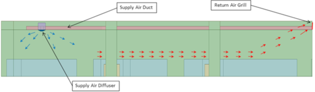
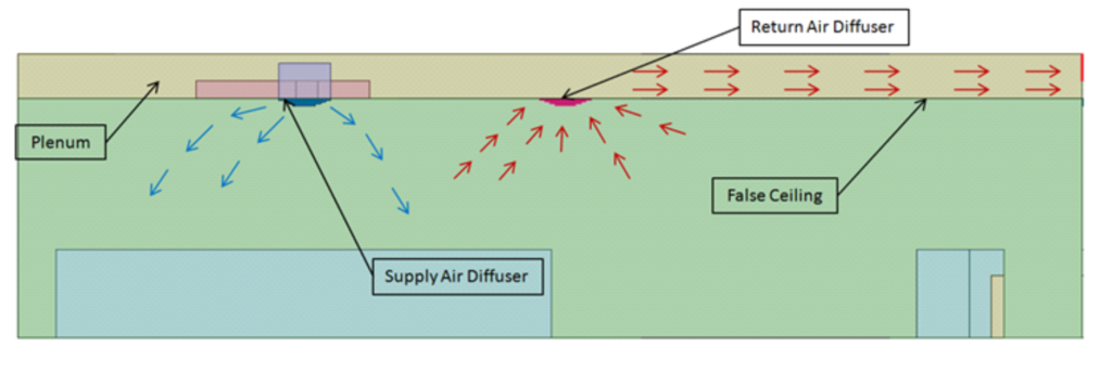
In this case supply air travels from the AHU through the supply air duct and enters the office space through the 4 way supply air diffusers placed throughout the office space. The conditioned air then collects the heat and contaminants and moves toward the return air through the occupancy zone. In this case there is only one return air close to the AHU. Image below provides a simple illustration of this HVAC system.
3D model of an office space with this HVAC system will be modelled along with the 3 infected persons placed at different locations.
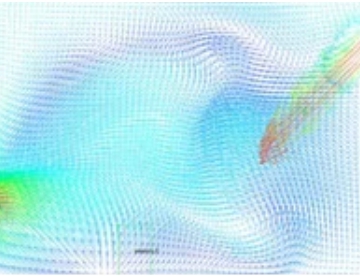
Flow Illustration of Case Study-01
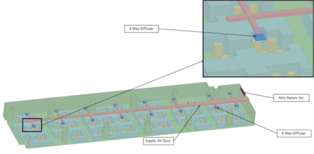
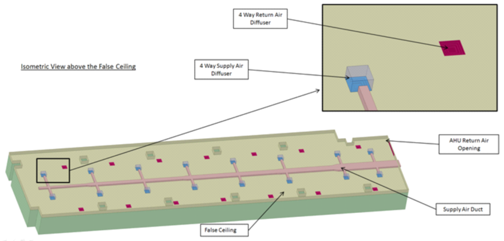
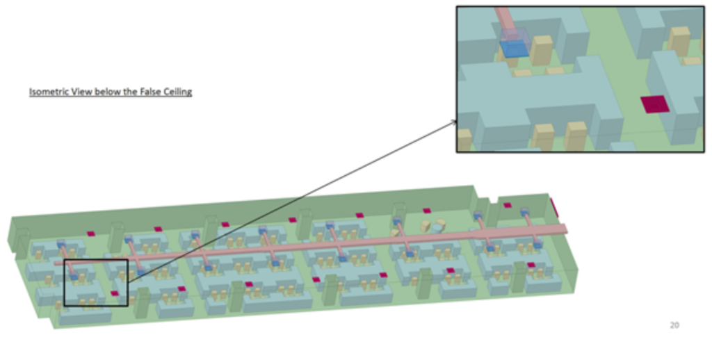
Isometric View of the Office Space in Case Study-01[3D Model]
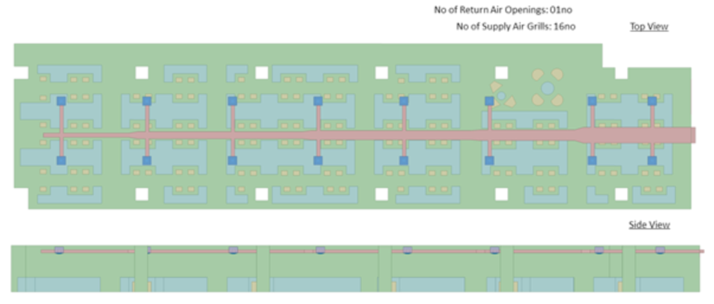
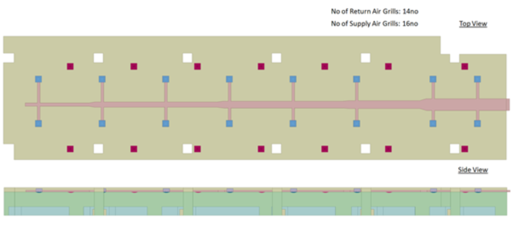
Top View & Side view of the Office Space in Case Study-01
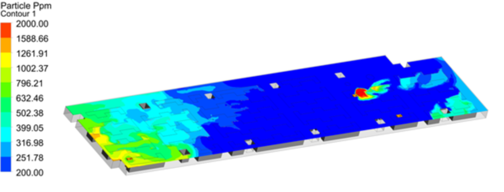
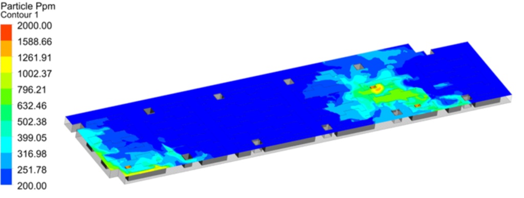
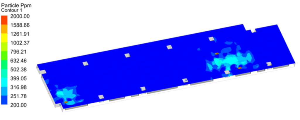
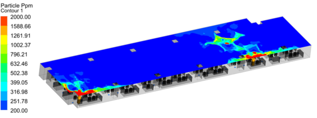
CFD Results- Particle Concentration Contour at 1m height
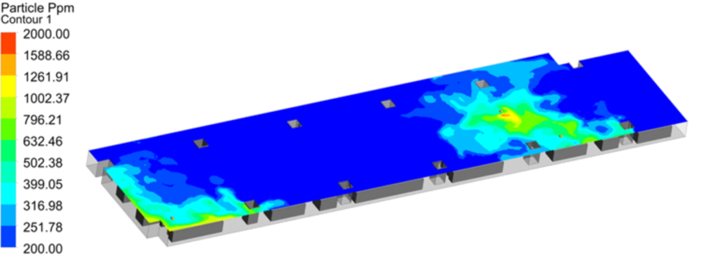
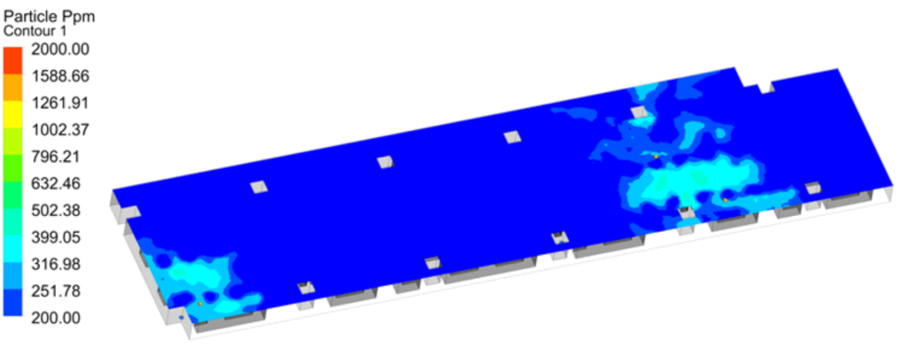
CFD Results- Particle Concentration Contour at 1.5m height
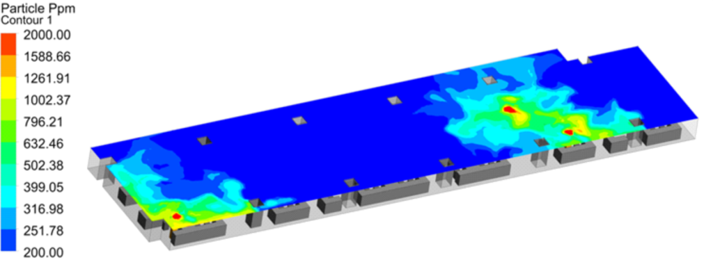
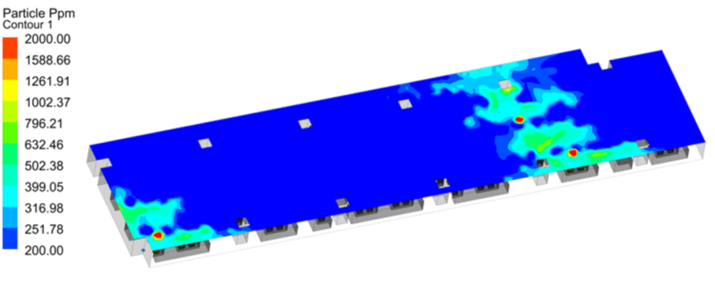
CFD Results- Particle Concentration Contour at 2m height
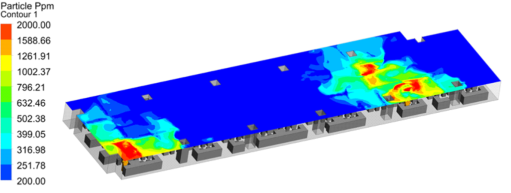
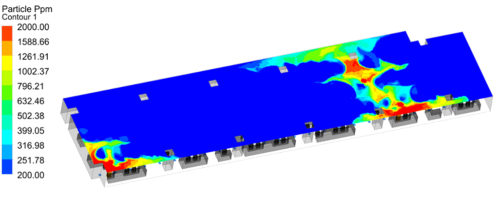
CFD Results- Particle Concentration Contour at 2.5m height
Following observations could be drawn from the CFD results of Case-01,
The infections from Person-01 could reach and plausibly infect half of the office space. Since the supply air moves towards the return air, the infected particles emitted by person-01 moves towards the return air. But due to turbulence and fluid mixing in the fluid domain, the contamination particles diffuse as it moves towards the return air. By the time it has reached the middle of the office space, the concentration of the particles have completely diffused. So the infection from person-01 has large spread distance. The concentration of contaminated particles are high close to the person-01 and reduced as we move away from him.
For Person-02 the spread and the concentration of the contaminated particles are low as he is sitting close to the return air. Since there is only one return air, the velocity close to the return air is high and hence it facilitates the effective removal of the contaminated particles.
For Person-03 the spread area of the infection is low due to his proximity to the return air. The concentration of contaminated particles is high close to person-03. It could also be seen that the CP move towards the return air through the occupancy zone, which means any one seated between person-03 and the return air had high risk of infection.
Case-02: HVAC System with False Ceiling
In this case supply air travels from the AHU through the supply air duct and enters the office space through the 4 way supply air diffusers placed throughout the office space. The conditioned air then collects the heat and contaminants and moves toward the return air 4 way diffuser paced throughout the office space, then the return air moves towards the AHU through the plenum (space above the false ceiling). Image below provides a simple illustration of this HVAC system.
3D model of an office space with this HVAC system will be modelled along with the 3 infected persons placed at different locations.
Flow Illustration of Case Study-02
Isometric View of the Office Space in Case Study-02 above false Ceiling [3D Model]
Isometric View of the Office Space in Case Study-02 below false Ceiling [3D Model]
Top View & Side view of the Office Space in Case Study-02
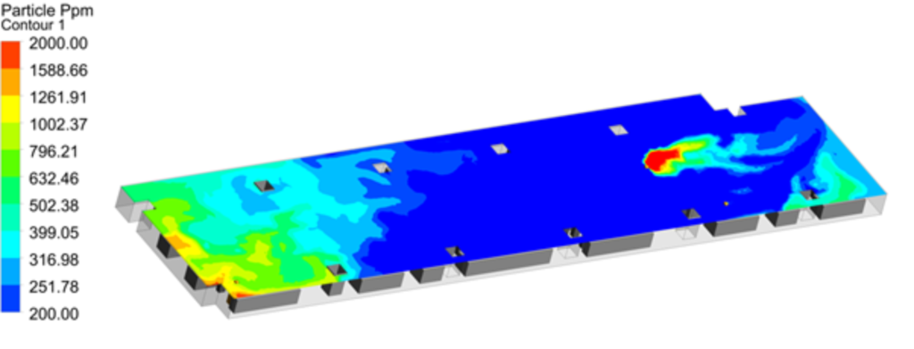
CFD Results- Particle Concentration Contour at 1m height
CFD Results- Particle Concentration Contour at 1.5m height
CFD Results- Particle Concentration Contour at 2.0m height
CFD Results- Particle Concentration Contour at 2.5m height
Following observations could be drawn from the CFD results of Case Study-02,
When compared to case-01, the infection from person-01 has reduced drastically in terms of both spread area and concentration of infection. This is due to the presence of localised return air diffusers. The air from one supply diffuser will try to move towards the nearest return air diffuser, hence the flow is localised. The spread from preson-01 is in the range of 10-15m in all directions.
For person-02 & 03, the concentration of CP has reduced but the spread has comparatively increased due the absence of a single large return air grill with high velocity. The increase of the spread area is due to the movement of CP towards multiple return air diffusers. This results in diffusion of the CP concentration due to fluid mixing & turbulence.
Case-03: HVAC System with False Ceiling & Raised Floor Supply Air Grills
[ Return air Grills: 22no , Supply Air Grills: 78no]
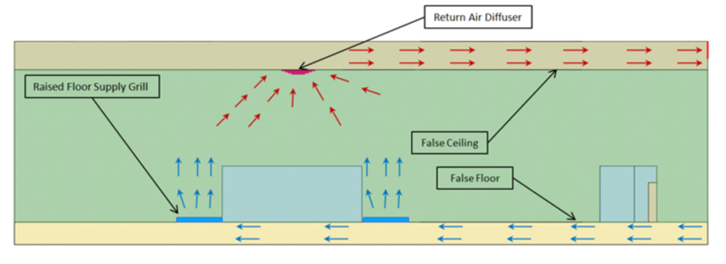
In this case supply air travels from the AHU through the supply air plenum(space below the false floor) and enters the office space through the raised floor grills placed throughout the office space. The conditioned air then collects the heat and contaminants and moves toward the return air 4 way diffuser paced throughout the office space, then the return air moves towards the AHU through the plenum (space above the false ceiling). Image below provides a simple illustration of this HVAC system.
Flow Illustration of Case Study-03
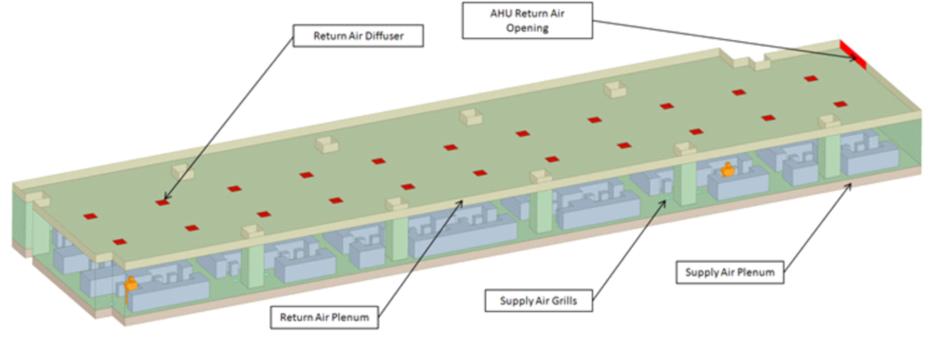
Isometric View of the Office Space in Case Study-03 above false Ceiling [3D Model]
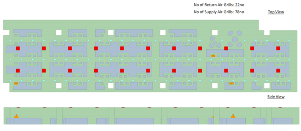
Top View & Side view of the Office Space in Case Study-03
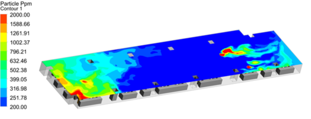
CFD Results- Particle Concentration Contour at 1m height
CFD Results- Particle Concentration Contour at 1.5m height
CFD Results- Particle Concentration Contour at 2.0m height
CFD Results- Particle Concentration Contour at 2.5m height
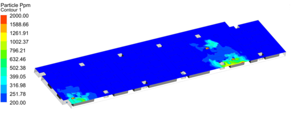
Following observations could be drawn from the CFD results of Case Study-03,
When compared to case-01 & 02, the infection from person-01,02 & 03 has reduced drastically in terms of both spread area and concentration of infection. This is due to the presence of localised return air diffusers & supply air grills. The maximum spread from all the 3 infected persons is in the range of 5m in all directions.
Case-04: HVAC System with False Ceiling & Raised Floor Supply Air Grills
[ Return air Grills: 44no , Supply Air Grills: 78no]
This case is similar to case study-03, with the only difference in the number of return air diffusers. In case-03 the number of return air diffusers are 22no and in this case the return air diffusers are increased to 44no.
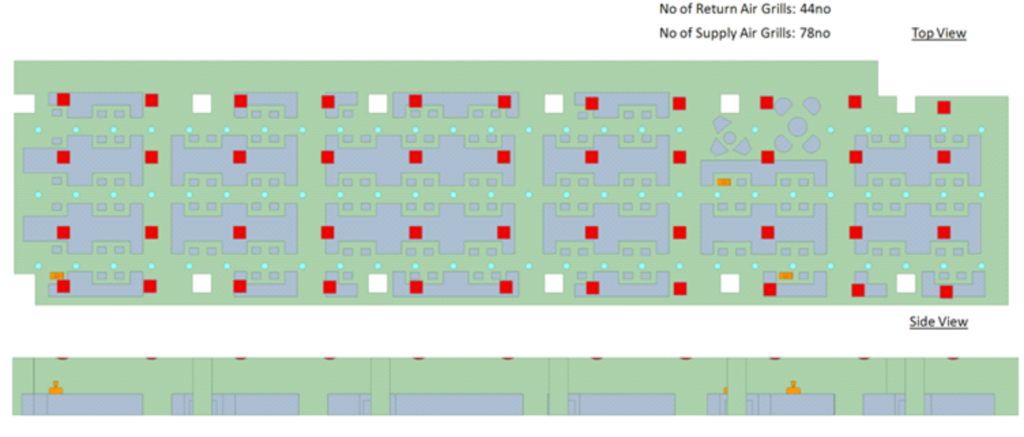
Top View & Side view of the Office Space in Case Study-04
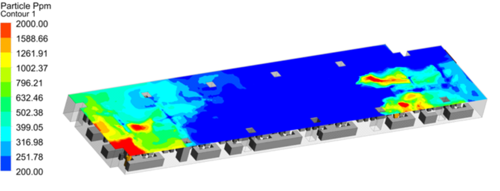
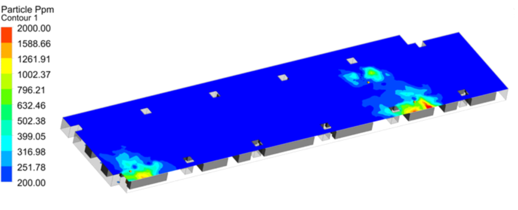
CFD Results- Particle Concentration Contour at 1m height
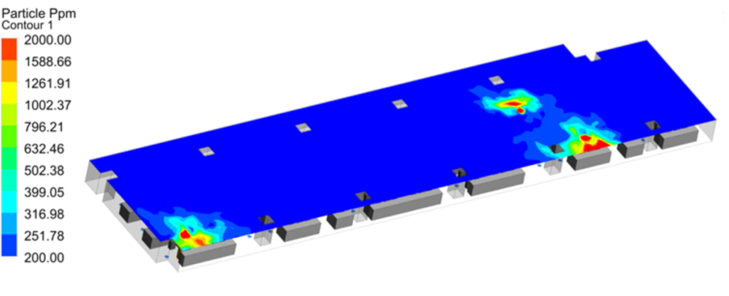
CFD Results- Particle Concentration Contour at 1.5m height
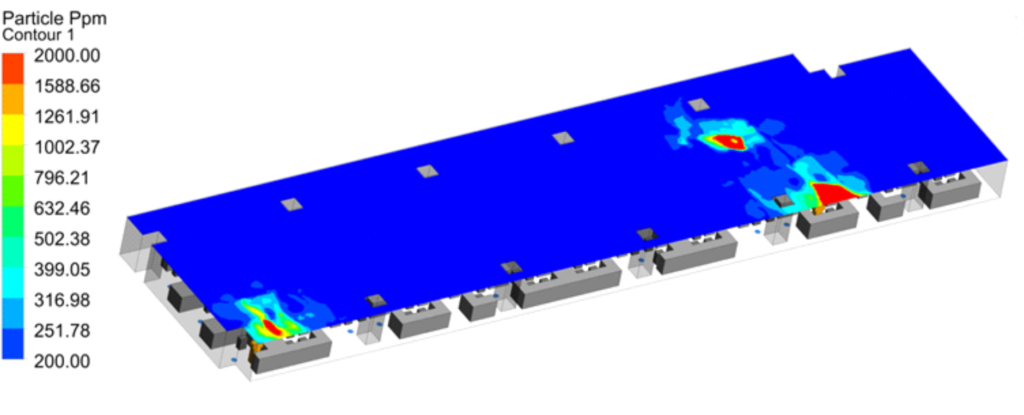
CFD Results- Particle Concentration Contour at 2m height
CFD Results- Particle Concentration Contour at 2.5m height
Following observations could be drawn from the CFD results of Case Study-04,
The increase of return air diffusers have further reduced the spread area & concentration of CP. This is due to the increased localization of the flow.
Case-05: HVAC System with False Ceiling & Raised Floor Supply Air Grills
[ Return air Grills: 77no , Supply Air Grills: 78no]
This case is similar to case study-03 & 04, with the only difference in the number of return air diffusers. In case-03 & 04 the number of return air diffusers are 22no and 44no respectively. In this case the return air diffusers are increased to 77no.
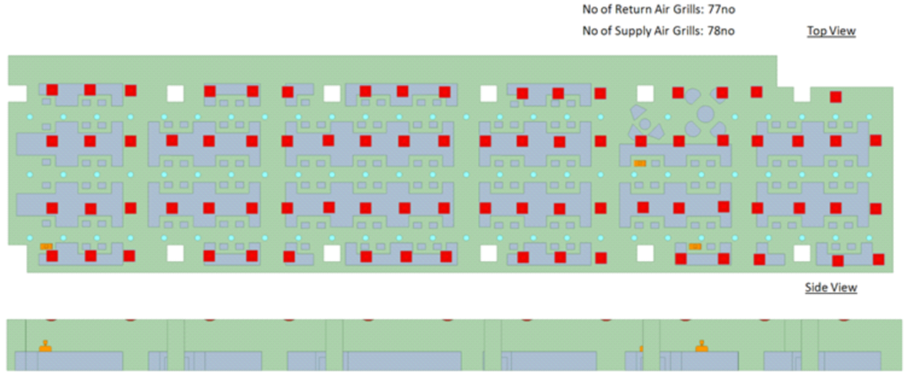
Top View & Side view of the Office Space in Case Study-05
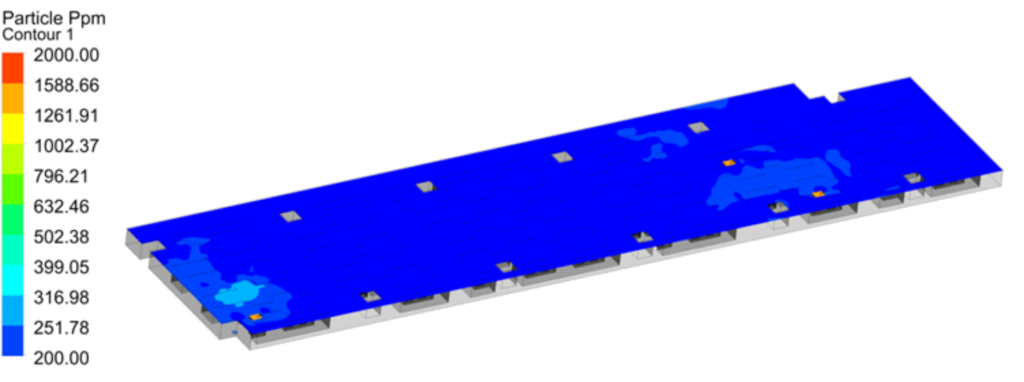
CFD Results- Particle Concentration Contour at 1m height
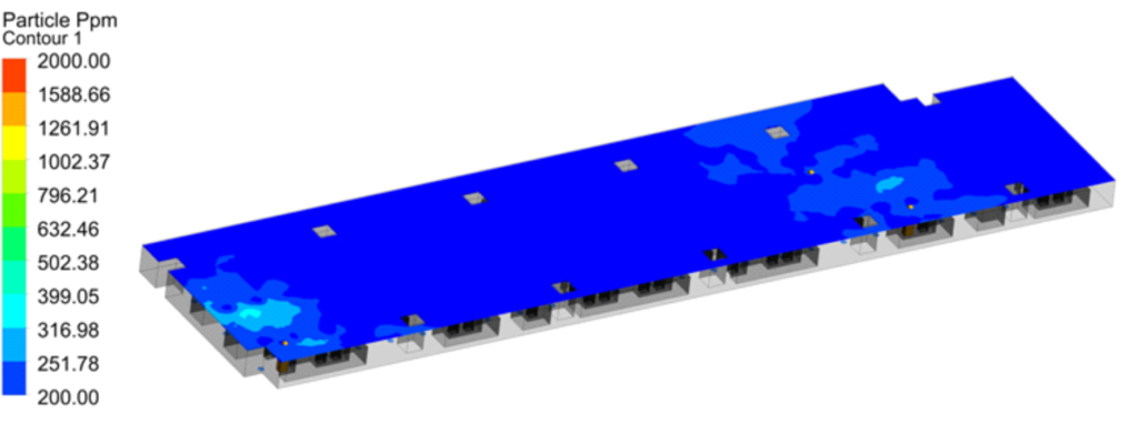
CFD Results- Particle Concentration Contour at 1.5m height
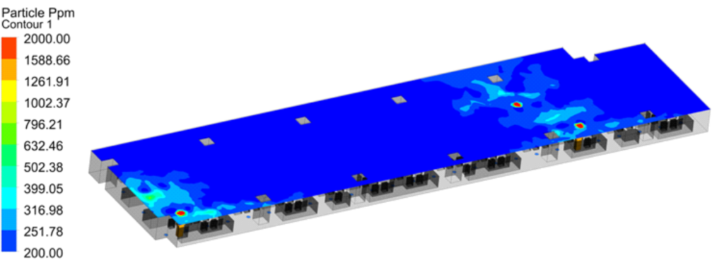
CFD Results- Particle Concentration Contour at 2m height
CFD Results- Particle Concentration Contour at 2.5m height
Following observations could be drawn from the CFD results of Case Study-04,
The increase of return air diffusers have further reduced the spread area & concentration of CP. This is due to the high localization of the flow.
Results Comparison
The results from all the 5 cases are extracted and plotted in the form of graphs side by side for ease of understanding and to make quantitative comparison of all the cases. Graph-01 plots the maximum concentration of CP in all the 5 cases & Graph-02 plots the area of contamination spread. It could be seen that case-01 has substantially high concentration of CP & spread area when compared to other cases. This is due to the fact, since there is only one return air, most of the CP remain inside the office space and hence increasing the overall concentration. In case-02, by introducing a false ceiling and adding multiple return air diffusers the overall CP concentration has been reduced by half and the spread area has been reduced substantially. In case-03 the concentration & the spread area has further reduced by increasing the number of return air diffusers, this is due to the fact increasing the supply and return air points will make the flow highly localised and hence reduces the overall travel distance of the CP. In the case-04, the concentration of CP has substantially reduced by the use of floor mounted supply grills and ceiling mounted return air grills. It should also be noted that the spread area has reduced but not substantially in case-04 compared to case-03. In case-05 the concentration is at a minuscule level and the spread area is at the lowest of all the cases.
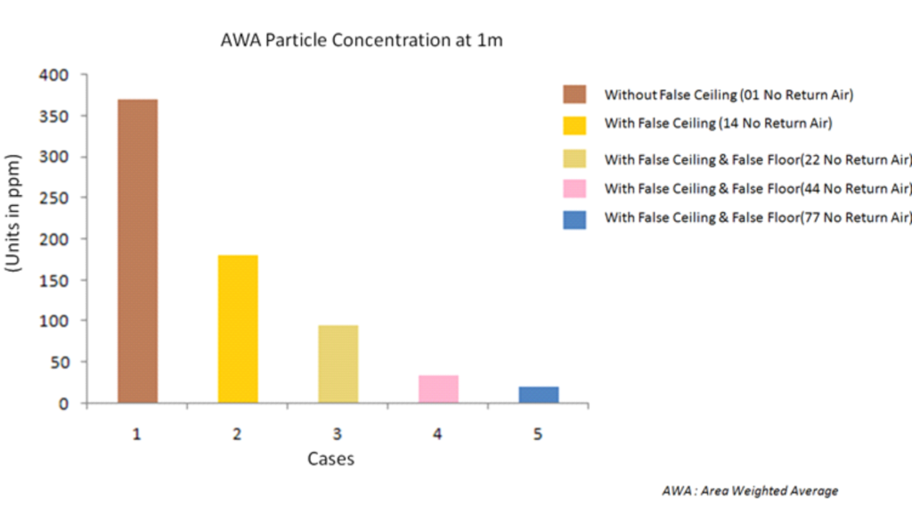
Area Weighted Average of Contaminant Particle Concentration
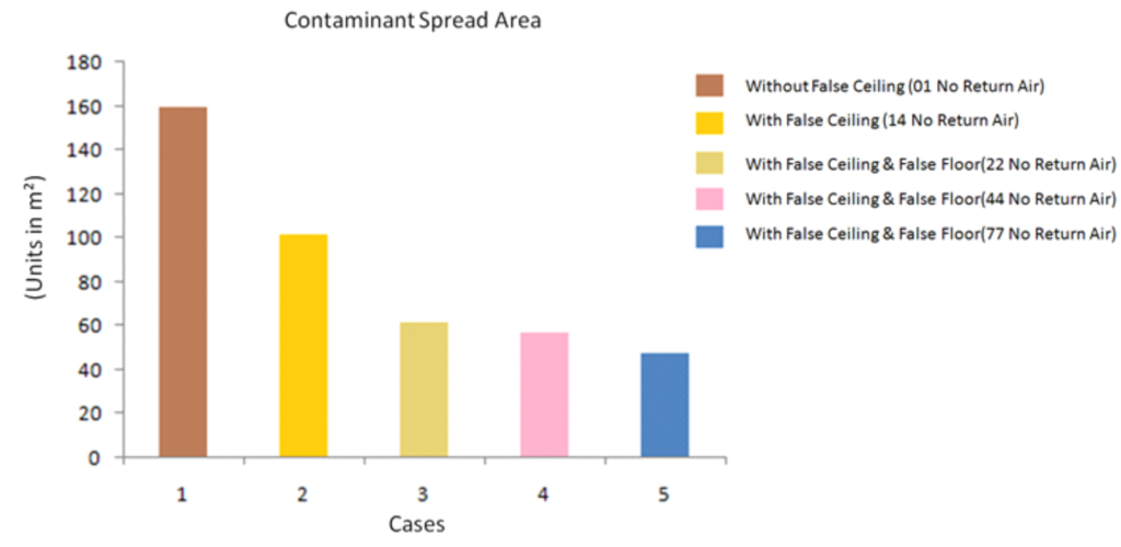
Area of Contaminated Particle Spread
Design Recommendations Based on this Fluid Dynamics Study:
It is no less important to reiterate the fact that in all the 5 cases, the flow rate of supply/return air, geometry of the building along with its furniture, concentration of CP emitted by the infected persons, location of the infected persons all remains the same. The only variable in these case studies are the type of air distribution systems. But still we can see vast differences in the probability of infection in all these cases.
Return air extraction by using return air ducts or plenum reduces the probability of infection substantially. Or can we say having a single return air point in a large office space, will substantially increase the probability of infection.
Increasing the number of supply air & return air points will further help in mitigating the infection rate.
Placement of floor or furniture mounted supply air points will be effective if placed correctly, taking into account the geometry of the area of interest and the location/size of return air diffusers.
Conclusion
There are number of studies conducted to understand the physics of contaminating transmission and ways to prevent them. There are number of recommendations made by different health and safety regulatory agencies to prevent the spread of infections. It is to be noted that the above recommended design practices are not to replace the recommendations and guidelines prescribed by health and safety regulatory agencies but rather to compliment them. We sincerely hope that this humble study will make a small contribution in reducing the spread of COVID and help humanity overcome this great suffering.

Author
Antony
Director – CFD Operations